• 車種別
  • パーツ
  • 整備手帳
  • ブログ
  • みんカラ+

SW20jiroのブログ一覧

2011年10月17日 イイね!

PG-11: VALVE LIFTERS AND CLEARANCE (1ZZ lifters in a 3S!?)


ALL NEW STOCK MR-S 1ZZ-FE LIFTERS

$224 for all 16 lifters at www.LithiaToyotaParts.com
-TOYOTA OEM MR-S VALVE LIFTERS - See below for part numbers


There're 3 different types of OEM lifters available to fit the 3SGTE motor! There's the gen2 3SGTE lifter, which is the outer-shim type. (See left lifter in photo) Then there's the gen3 3SGTE lifter, which is the inner-shim type. (See middle lifter in photo) And then there's the shimless MR-S 1ZZ-FE motor lifter, which has the shim incorporated into the lifter! (See right lifter in photo) This will be the "chosen one" for this rebuild! 


The gen2 lifter has the largest/heaviest shim, which is nestled on top of the lifter. This design can cause problems at high RPM's with aggressive cam lobes. That's because the cam lobe can flick the shim out when things are getting crazy in the valvetrain!

So to eliminate that problem, the revised gen3 lifter places the shim on the inside, so that it sits between the valve stem and the lifter rather than on top. For this set up, you will need to spend the extra effort to install the gen3 retainers. These retainers are important because they are cupped to hold the small shim in place. A bit of a pain to get this setup going, but at least you won't have to worry about shims taking flight inside the head! Plus the smaller sized shim of the gen3 setup reduces the valvetrain weight ever so slightly.


And now for the ultimate shim design! In the 1ZZ motor, they did away with the shim all together! Toyota made the lifters with the shims "built-in" exactly where the gen3 shims would be located. So no shims to worry about! Plus, this design also makes the lifter even lighter; making it the most favorable setup!

To convert to this sweet setup, the old 3SGTE lifter/shim needs to be measured and replaced with the correct MR-S lifter size. (The retainer can be gen2 or 3) The MR-S lifter size is printed on the inside, which is an underlined 2-digit number. (See right lifter in photo) Just put a 5 and a decimal in front of the printed number and that's the lifter thickness. So in this photos case, it's a 5.14mm thick lifter! 


You can see that all the lifters have the same diameter. 31mm, minus a little bit for oil clearances. 


With each revision, the lifter shaved some weight. The MR-S lifter is about 16.5g lighter than the gen2's design, that's 264g total if you consider all 16 lifters within the head! 


After deciding to go with the MR-S valve lifters, it was time to figure out which ones to order to get the valve clearance in working order.

It's important to keep the valve clearances in check. This will ensure the valves open and close correctly for the best performance. If the clearance is too tight, the valve may not close all the way because the lifter will constantly ride the cam lobe. With the valve not fully closing, it will overheat and burn because now the valve face won't make contact with the relatively cooler valve seat to transfer heat. But on the other hand; too loose of a clearance and the valve will not open all the way. This will hinder the flow of exhaust/air, while creating more wear on the valvetrain.

There are a few things that will affect the valve clearance on this rebuild. One is the use of the different camshafts from the rev4 SW20. This is because they could vary in diameter, but usually it won't change things up too much. The other, more critical factor is using the aftermarket valves! 1: because the valve lengths could vary slightly. And 2: because the valve job required for installing new valves will cut away at the valve seats to create a proper seal! This will totally throw off the valve clearance.

So now it's time to check the valve clearance and get it where it needs to be using the MR-S lifter setup, rather than buying new gen2 shims. The MR-S lifters are only a few bucks more than the shims, and are much lighter. So it's a pretty sweet alternative! But before starting this operation, make sure the engine is dead cold! The measurements need to be taken with all the engine parts cooled down. 


To adjust the valve clearance using the 1ZZ lifters, you follow a simple formula:


"3SGTE Lifter/Shim Thickness"  + "Feeler Gage Thickness"  -  "Desired Clearance"  =  "Required 1ZZ Lifter Size"


All that needs to be done is to figure out what each thickness is and plug it into the formula. The first part, "3SGTE Lifter/Shim Thickness" is the thickness of the currently installed 3SGTE lifter and shim combined. So pull out the micrometer and measure the lifter & shim together. (The lifter will fit a 1 inch micrometer) This one measured up to be 5.262mm thick, so that number will be plugged into the formula. 


After measuring all the rest of the lifter/shims, put them back to where they came from. Keeping track of what goes where, and what thickness each lifter is will be key here. So take notes or mark the parts and head if need be. 


The next part of the formula, "Feeler Gage Thickness”, is the current clearance you have between the cam lobe and lifter/shim. To check this, install the camshaft with the bearing caps and torque with the correct sequence! Then use a feeler gage to check the clearance between the cam lobe and lifter/shim as follows:

Check these 8 valve clearances with the #1 piston at TDC if the engine is still together. If the head is removed, then just rotate the cams until these cam lobes are loose so they can be checked. *WARNING: Make sure not to bend the valves if the head is removed, as the valves will open and close! You don't want it sitting on a table or have something in the way of the valves!* 


Then check these remaining 8 valve clearances with the #4 piston at TDC. If the head is removed, do the same thing as earlier! Notice the recommended valve clearances, when cold, are underlined in red as well! 


The intake valve, which had the lifter that I measured earlier, came up to be 0.095mm. So now I can put that into the formula. 


The last part of the formula, "Desired Clearance”, is the amount of clearance you want. Using the specs from the manual, you could determine what that is real simple. Just shoot for the middle of the clearance range: INTAKE would be 0.20mm and EXHAUST would be 0.33mm.

Since the valve I was checking, for the purpose of this demonstration, was an INTAKE valve, I would use the 0.20mm for the formula. However, since I have just gotten a valve job with brand new valves, I want to take into consideration the break-in factor. What I mean is that after running the motor for a while, the new valves will "seat" into the freshly cut valve seats, and that would cause the clearances to drop and get tighter. We're talking real low numbers here, maybe 0.02~0.03mm or so. So instead of going for 0.20mm of clearance, I will opt to go with 0.22mm of clearance, so that when the valves seat-in, the clearances will hopefully be around 0.20mm.


So now to put the formula into action:


"3SGTE Lifter/Shim Thickness (5.262mm)"  + "Feeler Gage Thickness (0.095mm)"  -  "Desired Clearance (0.22mm)"  =  "Required 1ZZ Lifter Size (5.137mm)"


Now we take that 5.137mm size and try to find the closest match available from the list of 1ZZ lifters, which would be the 5.14mm:

PART #----------SIZE
13751-46030 = 5.06mm
13751-46040 = 5.08mm
13751-46050 = 5.10mm
13751-46060 = 5.12mm
13751-46070 = 5.14mm
13751-46080 = 5.16mm
13751-46090 = 5.18mm
13751-46100 = 5.20mm
13751-46110 = 5.22mm
13751-46120 = 5.24mm
13751-46130 = 5.26mm
13751-46140 = 5.28mm
13751-46150 = 5.30mm
13751-46160 = 5.32mm
13751-46170 = 5.34mm
13751-46180 = 5.36mm
13751-46190 = 5.38mm
13751-46200 = 5.40mm
13751-46210 = 5.42mm
13751-46220 = 5.44mm
13751-46230 = 5.46mm
13751-46240 = 5.48mm
13751-46250 = 5.50mm
13751-46260 = 5.52mm
13751-46270 = 5.54mm
13751-46280 = 5.56mm
13751-46290 = 5.58mm
13751-46300 = 5.60mm
13751-46310 = 5.62mm
13751-46320 = 5.64mm
13751-46330 = 5.66mm
13751-46340 = 5.68mm
13751-46350 = 5.70mm
13751-46360 = 5.72mm
13751-46370 = 5.74mm


You would do the same for the rest of the valves and then make the purchase!

Here is the MR-S 1ZZ lifter installed, compared to the Gen2 lifter & shim. 


Once all the MR-S lifters are in, make sure they rotate freely and do a final check of all the clearances to ensure everything is good to go! And now the engine will love you for shaving 264g of unwanted fat from the valvetrain!


Next Pg: つづく。。。。
Return to Pg-1:
https://minkara.carview.co.jp/userid/1308078/blog/24157663/
Posted at 2011/10/23 04:57:44 | コメント(0) | トラックバック(0) | クルマ
2011年10月16日 イイね!

PG-10: COMBUSTION CHAMBER CC (What's the volume?)


MEASURING THE COMBUSTION CHAMBER VOLUME


Time to see what the combustion chamber volumes are! The cubic centimeters (cc) of each chamber will be higher because of the concaved Ferrea valves and because of the chambers being ground & smoothed out. The valve seats being freshly cut can also increase the volume as well since the valves will sit a bit deeper into the seats now. It's important to get the correct cc of each combustion chamber in order to figure out how thick of a head gasket will be needed to obtain a desired compression ratio.

Another reason to cc the chambers is to see any differences between the 4 combustion chambers which would take away from peak performance ever so slightly. Afterall, each chamber has been modified, so there is a good chance of having some differences. Any difference under 1cc is said to be fine, others argue 0.6cc is needed. But it's all up to you on how close the numbers need to be. To get an idea of what some tolerances are, some shops provide balancing services to get the difference within 0.4cc. Some even within 0.2cc! All for around a 100 bucks. So I'll shoot for 0.3cc, since it's some pretty tedious business.

And the last reason to cc the chambers is because it's pretty fun! It's sweet to master new things, you can teach your buddies later on when they need help figuring out a good head gasket. And they'll be like, "Wow, I totally owe you a beer dude!"


To cc the combustion chambers, some chemistry type items will be needed:

BURETTE w/ PETCOCK:A burette (a graduated cylinder) with a petcock (the attached valve) will be used to pour fluid into the chamber. It also measures the amount that went into the chamber too. So a burette that can hold more fluid than the volume of the combustion chamber will make things super simple. And for accuracy, fine increments below 1ml is key! The OEM MR2 turbo engine chamber volume is about 50cc (from what I've read and heard). Since 1cc equals 1millileter, a burette that holds more than 50ml is required! I happen to have a 100ml plastic burette with 0.2ml increments. This thing will give accurate readings! Much better than any crappy syringe method will yield. Higher quality glass burettes are available everywhere as well. But the price will most definitely change your mind about DIY cc'ing! Plastic ones are a little hard to find, but are totally kick-butt when it comes to the price tag. I got mine from a chemistry specialty store in Japan, but I've seen them in Amazon.com too. (see photo below: green tube in the middle)

BURETTE STAND: An adjustable stand for the burette is a must to hold it steady in place. (see photo below: white stand circled by red)

SYRINGE: A syringe can be used in place of the burette, but it won't be as near as consistant or accurate... I got mine from a sex shop with a kinky nurse costume from Rakuten.co.jp, but these are easy to find anywhere. When I'm not having fun using it for foreplay, it comes in handy for pulling the fluid back out of the chamber after taking a reading. It's also good for topping off the burette precisely, kinda like a pipette. The burette needs to be exactly filled to the 0ml mark prior to cc'ing, so the syringe can be used to do that with no problemos. (see photo below: item with sexy nurse circled by pink)

FUNNEL: A tiny glass funnel to fill the burette is real helpful. (see photo below: item circled by yellow)

BEAKER: A graduated beaker to hold fluid is good to have as well to hold and transfer fluid. I have a 100cc beaker. (see photo below: item circled by blue) 


ACRYLIC SHEET: Any flat, thick plastic sheet will work really, as long as it is thick enough not to flex during the procedure. It needs to be big enough to cover the chamber since it will be used to cap it off. This way the fluid will not spill out all over. Get your sheet and drill a hole big enough for the petcock to fit, but not air tight. This hole needs to be slightly bigger to allow the air to escape during the process.

GREASE: Any grease to put between the plastic sheet mentioned earlier and cylinder head will be fine. It will provide a seal so the fluid won't leak out. I happen to have mobil 1 synthetic grease on hand, and it works like a champ. Personal lube like KY-Jelly or Anal-Ease might not work so well, but who knows?

FLUID: The fluid is used to measure the volume. Something that won't rust or leave a mess is something to consider when choosing a liquid. And you wanna have some coloring to make it easier to see. Like alcohol with green food coloring! But I didn't want to dry out the rubber o-rings in the petcock with alcohol, plus I don't have any except shōchū and I don't want to waste that. So I used some coolant with distilled water which I had laying around. If you use antifreeze, it's easier to wipe up the chamber after a reading if you mix more water into it to make it less viscous. 100% antifreeze is tougher to soak up with rags, it's like watery syrup... This is important because a few checks should be done per combustion chamber until a consistant reading is achieved, so there will be many wipings; considering all 4 chambers..... 


With all the junk needed at hand, the process can finally be put into gear. Here is an example of how to set things up. I have my burette stand on the top shelf of the bench and the burette has been filled with The-Secret-of-the-Ooze. Notice the right side of the cylinder head is tilt up to allow the air to collect to the right, this is where the hole in the acrylic sheet should go. Just do whatever is clever to get the head to tilt.


Lightly coat the valve faces with grease and push them into place. You can also cc the chambers with the head assembled (valves installed with the springs and retainers) as long as the valves are seated with no leaks. Also, clean sparkplugs need to be installed as well. Then put a light, even coat of grease around the chamber to provide a seal like so. 


Make sure to prime the petcock by opening it and letting fluid through prior to starting. This will fill the petcock with fluid, then close it and top off the burette back to the 0ml mark. If not done, the actual cc will be a tiny bit lower.

Now place and press down the acrylic sheet to create a seal. Then set up the burette so it is just barely going into the hole of the sheet.

Now all you have to do is open the petcock! The petcock will allow you to control the flow precisely. Pour fast at first, then slow towards the end to prevent over filling. Tapping the plastic sheet gently will help work air out if needed while pouring. 


Here is a quick video of the chamber being filled to see how things work. It should be done slower to prevent air bubbles however. And the reading at the end was a bit higher because the petcock wasn't primed prior to starting. 


After filling the chamber, the burette will display the amount that went into the chamber. Once that's been recorded, you can suck out the fluid through the hole with the sexy syringe with one hand and tilt the head more to move the fluid with the other hand. If you don't do this, the fluid will spill when removing the plastic sheet, so the syringe is pretty handy. You can also suck out most of the fluid trapped in the spark plug too with a fast pull of the syringe. 


The results were as follow:

chamber #_____1st attempt___2nd attempt
1____________________52.2cc___________52.2cc___
2____________________52.4cc___________52.4cc___
3____________________51.9cc___________51.9cc___
4____________________52.4cc___________52.4cc___

Everything is within 0.5cc, which isn't bad at all, but I would like everthing to be within 0.3cc. Since #2 and #4 has the highest volume of 52.4cc, this value will be used as the reference. So the goal is to increase #3 by 0.2cc to atleast a 52.1cc volume. #1 will be left alone since it is already within 0.2cc.

After carefully sanding the #3 chamber with #200 and #400 sand paper for aboout 15mins, another cc check can be done. This time the volume was consistantly at 52.0cc....

Back to sanding a bit more.... Now the volume was consistantly at 52.1cc. At this point, I did a quick polish job and did my final cc checks, a solid 52.1cc. (Polishing doesn't change the value) And now all the figures are within 0.3cc.

With all the valves sealing good, all cc's reading good, chambers & ports smoothed out, and cylinder head machined flat & smooth, it was time for a final polish before reassembling the head!

First, the hard stainless steel valves got a polish with the dremel tool using #320 then #400 then #600 grit compound. Followed by a final polish compound. The result is the intake valve on the right, compared to the untouched valve to the left.


After the other valves get polished, the aluminum chamber gets a final polish aswell using just the finishing polish compound. 


Do the same with all 4 chambers! 


All that's left is to touch up the exhaust ports and clean everything out of the cylinder head! And that does it for all the head work! ..... for now.... BEER TIME!


Next Pg: https://minkara.carview.co.jp/userid/1308078/blog/24252050/
Return to Pg-1: https://minkara.carview.co.jp/userid/1308078/blog/24157663/
Posted at 2011/10/23 04:43:07 | コメント(0) | トラックバック(0) | クルマ
2011年10月13日 イイね!

PG-9: MACHINE SHOP WORK (All the Machining is Complete)

COMPLETED MACHINE WORK


Back again from ADAM'S METALIZING! All the machine work is finito~!

So here's the head with a new valve job and the valves properly ground to mate perfectly with the seats! The head surface is also freshly cut and smooth for use with a multi layer steel head gasket. A minimum of 50 roughness average is required for those.


To make it more visible for the camera, laid down some Dykem layout fluid on to the valve face and the valve seat.


Place some motor oil on the valve stem and then lightly hand lap the valves with 400grit compound to see how they are seating. No drills or dremels! 


So here's the newly machined 3S block, and it features new freeze plugs!


It is nice and grease free, thanks to the spa treatment it received at ADAM'S METALIZING. You can see where Toyota stamped the main journal sizes on to the bottom of the block.


The cylinders have been over bored and honed to facilitate the 86.5mm SRP pistons. Notice the important crosshatch pattern for all the oil molecules to hang out and mingle! Don't mind the lint...


The surface was trimmed down flat with about a 37RA finish to handle a multi layer steel head gasket from Cometic!


To seal the deal on this block work, I chose to paint the block to help protect it as well as make it look sweet!

So first things first, hose the block down with paint thinner from a spray bottle and scrub away with a wire brush to get any layer of crud off! Used a dremel with a small wire brush piece for the hard to reach spots. Brake cleaner works good too.

Then, using some CLEAR engine enamel paint (like from Duplicolor), lightly sprayed the freeze plugs to prolong their shiny-ness.

Next, it was time for the tape-off stage! Using painter's masking tape, tape everything that should'nt be painted, like where the seals go and of course the block's surface.


And finally, it was time... To lay down some CAST IRON color engine enamel on this thing!! Don't forget the small areas on the bottom of the block as well... Remove the tape before the paint hardens all the way, and BAM!, the 3S block is look'n new! 


A little side story: Some old butt-head inspector in Japan, failed me during a vehicle inspection (called: SHA-KEN(shaken) = car inspection) for the 3S stamp being unreadable in my skittle-blue MR2! I had to go grab my skinny dremel, and clean away at the corrosion junk that partially masked the 3S stamp, with the motor still in the car of course, and in the rain... This block, however, shouldn't have any problems being read! 


Here is the before&after photos of the new and improved, slightly lighter OEM crank! It has been balanced to work with the lighter pistons & rods and the journals have been micro-polished. 


You can see where Toyota stamped the crank to identify the journal size. It's hard to see since the machine shop shaved some metal off from here to balance the crank down. 


Didn’t go for the lighter knifed-crank option for this engine build because I wanted to keep “some” weight on the rotating assembly for drivability purposes. The flywheel is already going to be a light-weight chromoly type after all.

Speaking of which, here is the resurfaced JUN Engineering chromoly flywheel, which has been dynamically balanced together with the Cusco reinforced clutch; both taken from the old Zokusha MR2! 3SGTE clutch/flywheels are interchangeable. 


Normally this clutch has a plain steel finish, making it blend in with the stock unit, but I had painted it candy blue to give it a more "Cusco'y look. Make sure to mark how the clutch cover was sitting on the flywheel so the balance doesn’t get thrown off! 


This reinforced regular Cusco clutch has been made by Exedy and has the royal stamp of Exedy here where it is circled. (kinda covered by the paint) 


Here is the comparison to the OEM clutch that was in this rev2 SW20.(after the oil was cleaned off) They are pretty much identical at first glance, with only slight differences. 


There is a difference in the weight of the clutch as well. The reinforced Cusco unit is about 1.2kg lighter while providing more clamping force! 


Here is the super-balls, OEM flywheel next to the totally sweet, Jun chromoly flywheel! The machine shop smoothed up the surface nicely and didn't have to mess much with the balance on the finely crafted flywheel. 


The chromoly flywheel is 2.59kg lighter than the OEM counterpart with the clutch bolts installed. 


And then, there are the flywheel bolts! OEM compared to the 12-point ARP Pro bolts. Had the machine shop balance up the drivetrain components with these ARP bolts which are 22.5g lighter. 


Last but not least, the assembled SRP Pro pistons and Carrillo A-beam rods. They are all equally balanced to weigh the same, and the rings installed with the proper amount of gap. 


Here is the cost for all the machine work:

Over bore and hone__________________$135
Block resurface_____________________$75
Head resurface_____________________$45
Valve grind/Valve seat job.____________$120
Clean all parts______________________$45
Balance and polish crank_____________$160
Resurface/balance flywheel/clutch______$40
Assemble/balance piston and rods._____$40

TOTAL____________________________$660


Next Pg: https://minkara.carview.co.jp/userid/1308078/blog/24252031/
Back to Pg-1: https://minkara.carview.co.jp/userid/1308078/blog/24157663/

Posted at 2011/10/16 11:12:05 | コメント(0) | トラックバック(0) | クルマ
2011年10月12日 イイね!

PG-8: HEAD WORK PART 1 (Port & Chamber Polish)

POLISHING THE PORTS AND CHAMBERS!


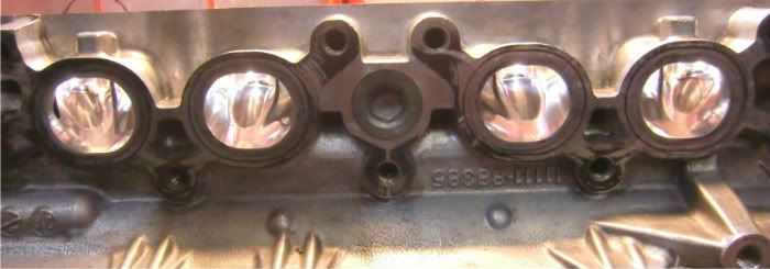
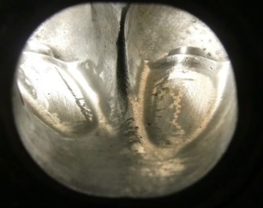
First things first, after evicting the carbon and junk from the ports and combustion chambers(if the machine shop bathing didn’t get it), rid all bumpy castings that would restrict the air flow in the exhaust ports. (Although irrelevant, you can see where the EGR system taps into the exhaust port for gases here. This was my first time seeing a 3SGTE head with EGR, kinda cool!) 


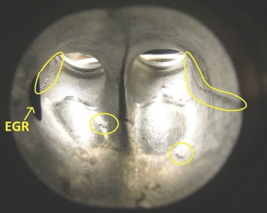
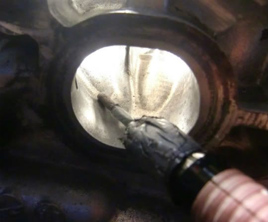
I like to use the trusty "Mini-Dremel of Devine Porting" with a medium grinding stone that's beveled! This isn't an actual Dremel brand, just a skinny version from another company I bought in Japan. (It's alot cheaper than a Dremel too!) The famous Dremel has a tough time fitting in the ports with its larger size, plus it’s heavy and kinda over powered which could scratch things more than you want. *TIP: Wrap some tape around the metal moving parts that could scratch the aluminum head like shown!* 


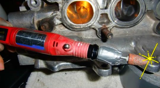
With a goose-neck lamp positioned like so, it makes it real easy to see what is going on inside the ports. Having some paper to cover the bulb helps to direct the light right into the head instead of in your face. 


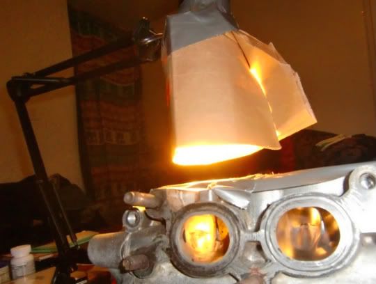
Generally, you don't want to enlarge the ports since that would just cause lower air velocities and hinder engine power. Just remove and blend away the casting bumps.  


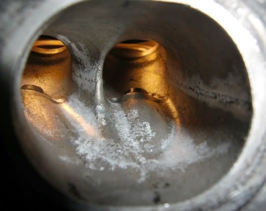
Using sandpaper and these sandpaper type grinders, try to blend everything out. Careful not to push too hard with the dremel tool, if the grinder piece is real rough,(especially with the strong wall outlet type Dremel) it will leave scratch marks that will be more difficult to remove than the pits and bumps in the head casting. This is where the light-weight dremel shines, it's nice and gentle. 


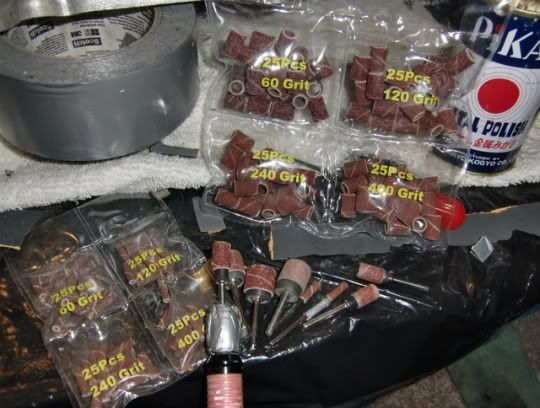
Next, buff things out a bit with this spinning scotch-brite piece. This is a good tool to use to see how the surface is looking.  


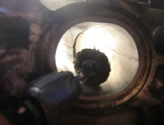
It will look like this when done, which took less than 15mins, start to finish. And is all that's really needed to get the air flowing!  


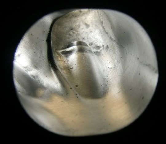
You could spend more time trying to get rid of the remaining casting pits, but it'll take way more time, like double! Plus you still got all the rest to do... This is all you really need to get the most air flow going while providing some surface roughness to help mix up the air/fuel. However, this is the exhaust side, so make it shiny, to prevent carbon build up! Work your way up with finer sandpaper (after 600grit and you should be good, but wet sanding with 1000grit is even smoother: how much effort are you willing to put?) Do the polishing part last, after all the sanding is done on all ports and chambers (cause it will get scratched up again).

Now to work on the other end, from the combustion chamber side. More bumpy castings! 


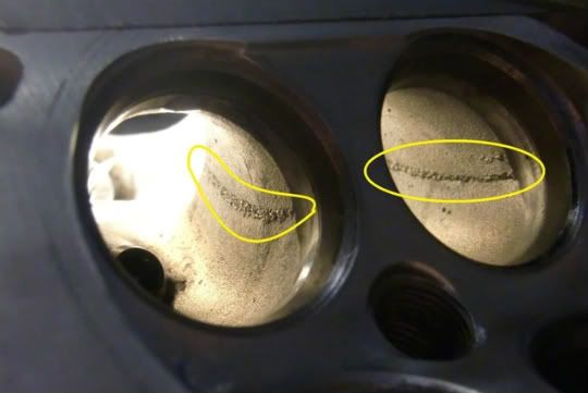
Grind and blend away those bumps on the exhaust and intake side, but be real careful not to scatch up the valve seats where the valves seal against or it is GAME OVER! 


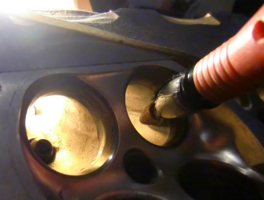
Try not to take away from the part just below the intake valve seats where it gets slightly narrow! This little part is a venturi and creates an area of higher air velocity for the intake port so it can cram and stuff that tight chamber with a huge load! Of air/fuel that is!! 


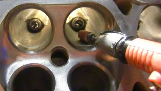
Now work the other end of the intake port where the injectors sit and blend away at the bumps!


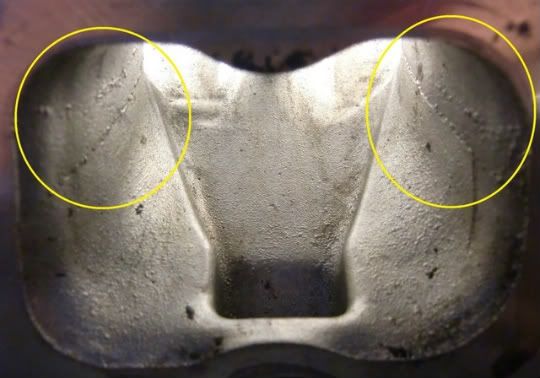
The mini-dremel has great reach! Repeat the process just like for the exhaust ports. 


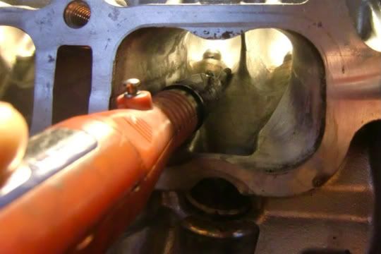
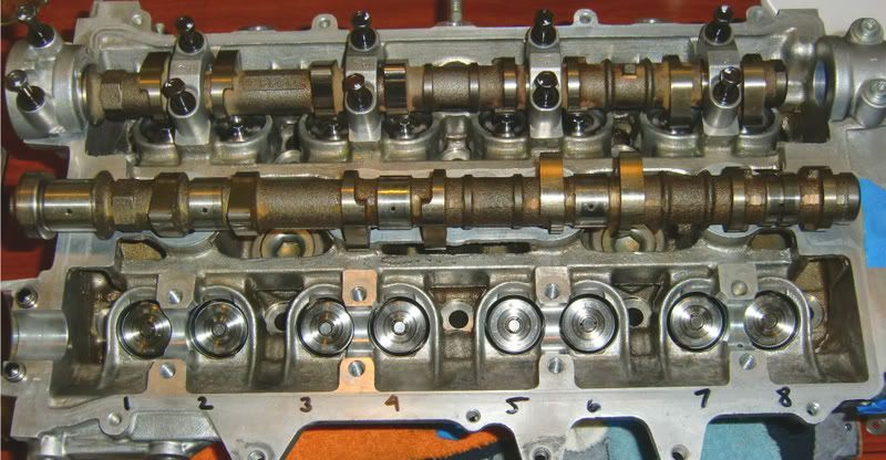
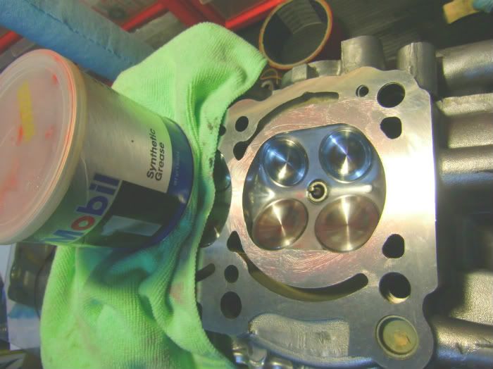
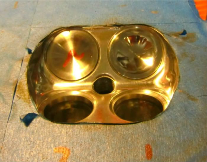
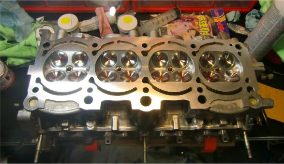
Now for the combustion chamber area! I remember the gen3 motor not having these valve seats poking out... They were smooth from the start.


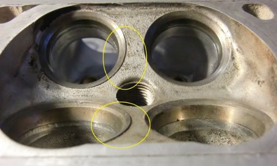
This really isn't a problem for the average motor, but I went ahead and ground away the sharp edges here on the valve seats. These, and any other high & pointy spots, are what can get real hot and cause unwanted detonation if the combustion chambers were pushed hard enough. They can act like mini glow-plugs. Careful again not to scratch the seats, as well as the head's surface!!! Tape up the head's surface so it is protected and prevents particles from getting inside. 


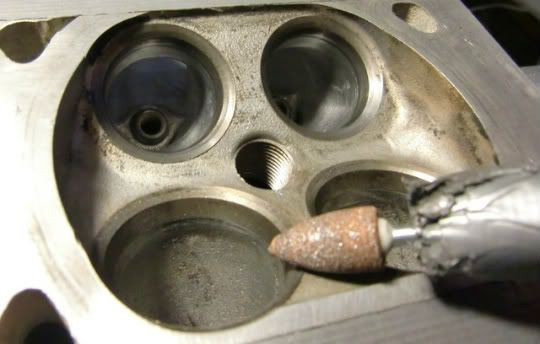
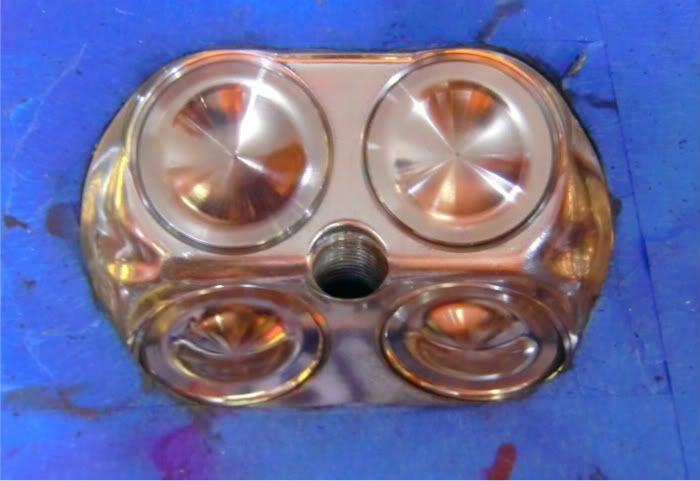
Now everything is flush with no pointy spots to get hot! 


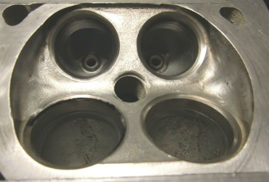
Now go to town with different grits of sandpapers and stuff to get the surface smooth! *TIP: Using the old unwanted valves to cover the rings will keep’m shielded from accidental scratches!!* 


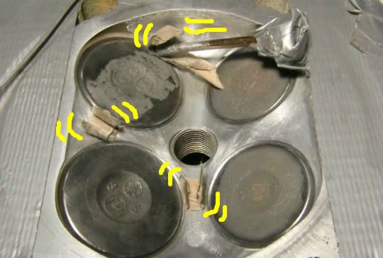
Buff out the surface with the scotch-brite tool again!


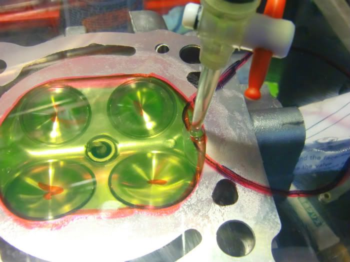
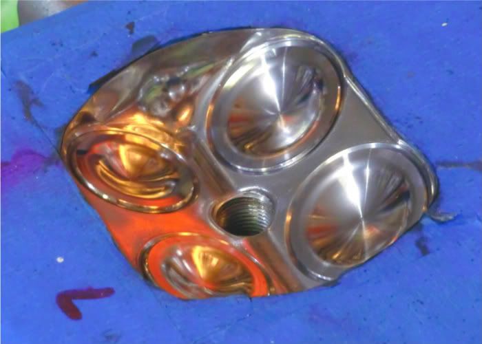
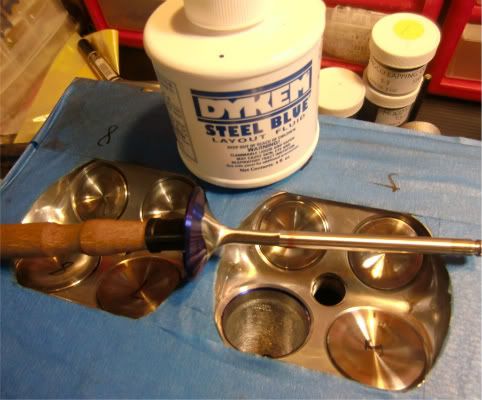
Now to polish everything with some polishing compound and some type of polish tip! This is my favorite part! 


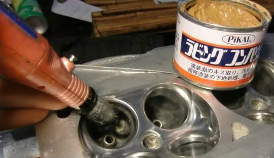
Polish the exhaust ports to make it slick so carbon won't build as easy! I use 2 different polishing compounds. A slighty rougher 1 first, then a more fine finishing compound next.  


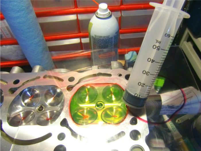
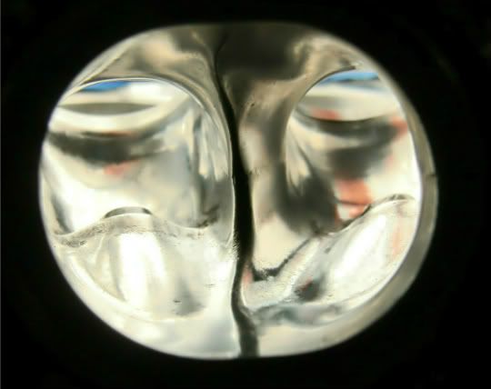
Then lastly, the intake ports! Leave a light rough finish after the injector if you want things to mix better. This was gently done with the 60grit grinder to leave a rough finish where the scratch marks are perpendicular to the air flow to help get the air rolling, and therefore mixing!  


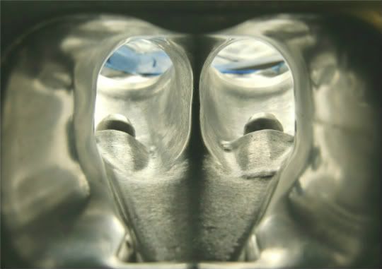
Lastly is to polish up the chambers! *TIP: Clean up the left over compound and polishing wheel peach-fuzz using lint-free micro-fiber clothes!* Don’t forget to clean out the valve guides too.  


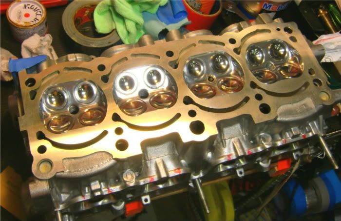
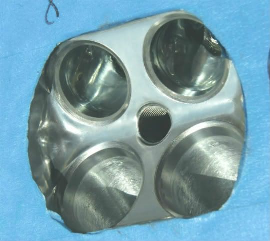
It would have been nice to port match but I am still deciding on which intake and exhaust parts to mate up with the head. So that will be skipped for now. Does anyone have any input on the T-VIS eliminating phenolic spacer???

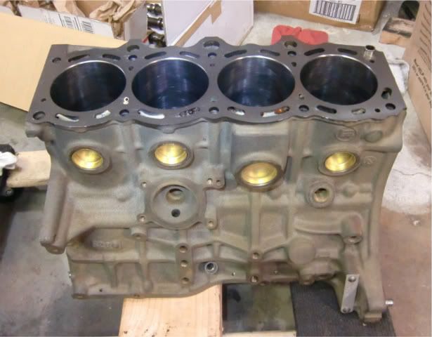
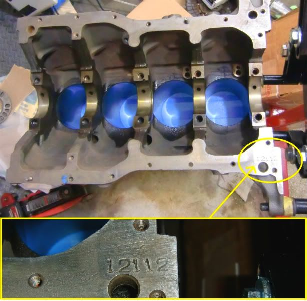
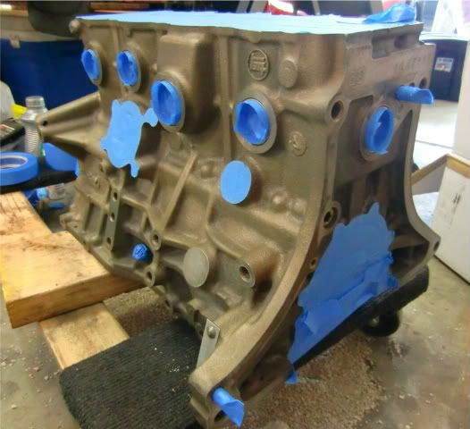
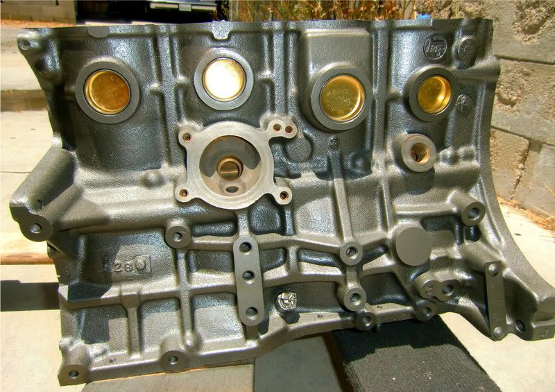
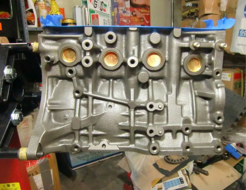
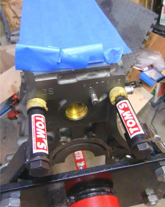
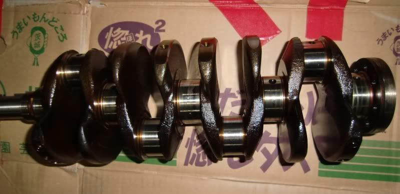
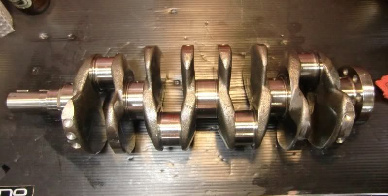
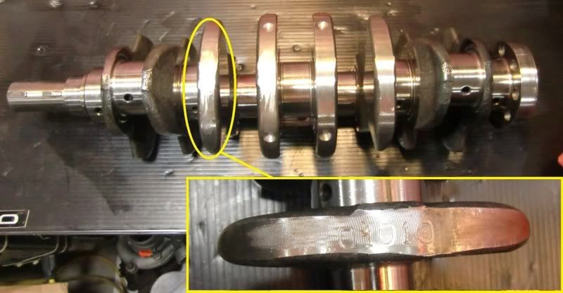
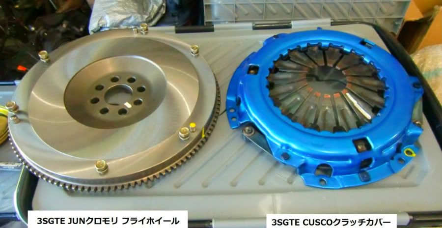
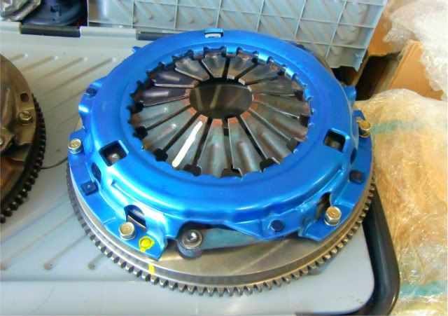
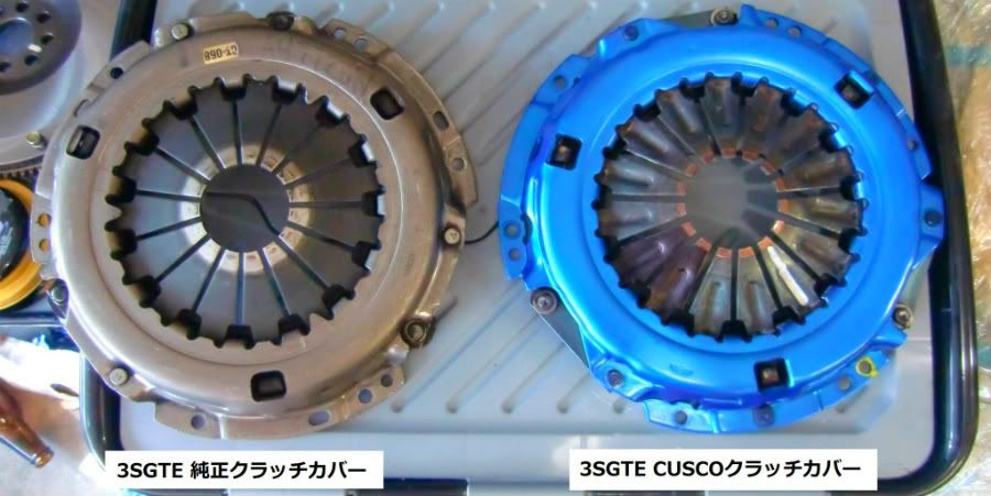
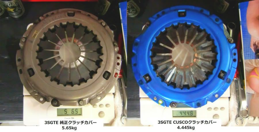
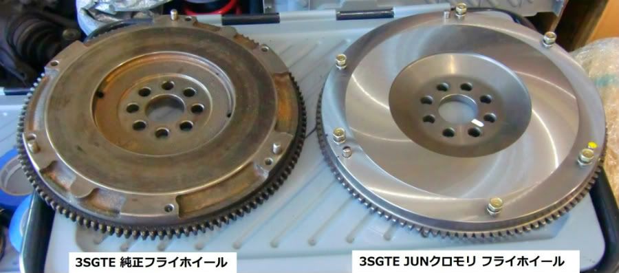
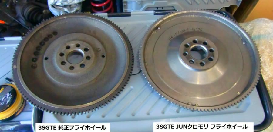
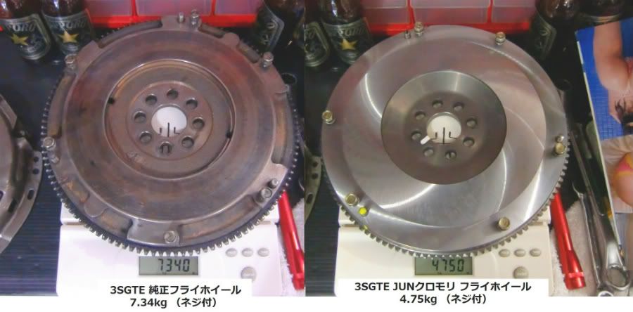
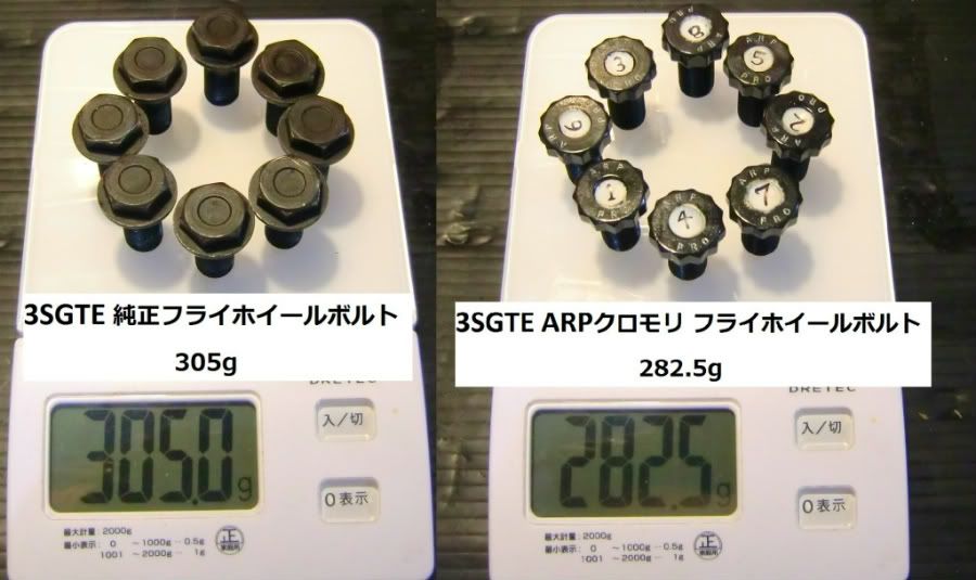
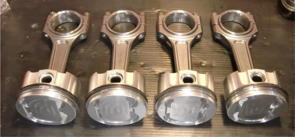
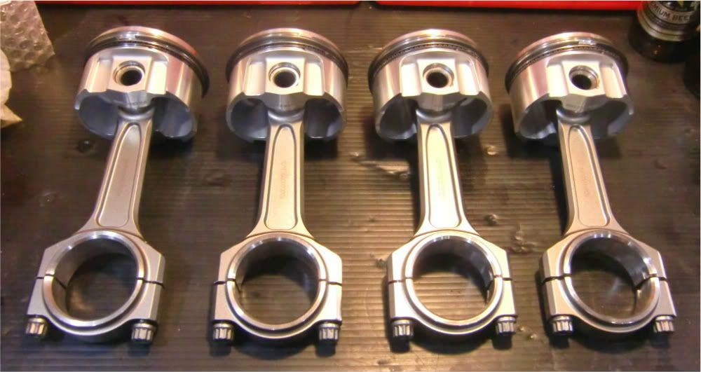
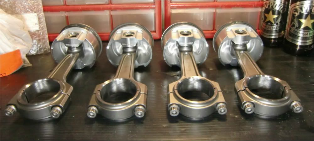
For now, it's time to take the head and block, along with the crank, flywheel, clutch, rev4 cams, and pistons & rods to ADAM'S METALIZING AND GRINDING to get machined and balanced!


Next Pg: https://minkara.carview.co.jp/userid/1308078/blog/24179169/
Back to Pg-1: https://minkara.carview.co.jp/userid/1308078/blog/24157663/
Posted at 2011/10/16 10:42:59 | コメント(0) | トラックバック(0) | クルマ
2011年10月11日 イイね!

PG-7: CAMSHAFT JOURNAL OIL CLEARANCE! (Using Plastigage)

HEAD WORK TIME!

It's time to check these scratched up camshaft bearings to see if they can support the rev4 MR2 camshafts before having the machine shop do up the head surface! Hopefully the oil clearances between the camshaft journals and bearings aren’t too loose from all the wear and tear this engine has been through...

The clearances need to be 0.025mm - 0.062mm to be within specs. But a max of 0.08mm is also allowed, kinda like a last resort. With the right clearance, oil pressure can build up to the proper amount and keep the camshafts nice'n lubed! But if the clearances are too large, oil pressure won't build; too little, and the oil won't even make its way through!

So to check the oil clearances, just place the oil free camshafts into the head after cleaning everything up. Don't want any particles or oil messing up the oil clearance readings! Then place some of the green plastigage down on each camshaft journal like so. 


With the plastigage in place, carefully install the clean camshaft bearing caps into their respective places without disturbing the plastigage. And with a little dab of oil on the bolt threads & heads, torque away to crush the plastigage!


With the caps torqued down in the correct pattern like shown, the plastigage will be smashed and spread out. The amount the plastigage is spread out will determine the camshaft journal clearance! 


Remove the caps in the correct pattern like shown to expose the smashed plastigage, which should be stuck to the camshafts. 


Compare the flatten plastigage width against the chart that is provided with the plastigage to find out what the oil clearance is! In this case, the clearances were all about 0.051mm, which is on the high side, but still good! Make sure to clean up the plastigage, and everything's a done deal!


Next Pg: https://minkara.carview.co.jp/userid/1308078/blog/24178923/
Back to Pg-1: https://minkara.carview.co.jp/userid/1308078/blog/24157663/
Posted at 2011/10/16 10:26:19 | コメント(0) | トラックバック(0) | クルマ

プロフィール

オッス!二郎です!USDMの2型SW20GT-Sに乗っています。なぜUSDMのMR2?それは仕事の移動のため、今はアメリカに住むことになったからで~す!日本にい...
みんカラ新規会員登録

ユーザー内検索

<< 2026/1 >>

    123
45678910
11121314151617
18192021222324
25262728293031

愛車一覧

トヨタ MR2 族車 (トヨタ MR2)
H6 3型 SW20 3SGTE ターボ
トヨタ MR2 名も無き (トヨタ MR2)
1993のUSDM MR2だよ~! T-VIS入りの3SGTEが入って立ち上がりが速い! ...
トヨタ MR2 ベイビーブルー (トヨタ MR2)
2型 ターボ ノーマルルーフ

過去のブログ

2011年
01月02月03月04月05月06月
07月08月09月10月11月12月
ヘルプ利用規約サイトマップ
© LY Corporation