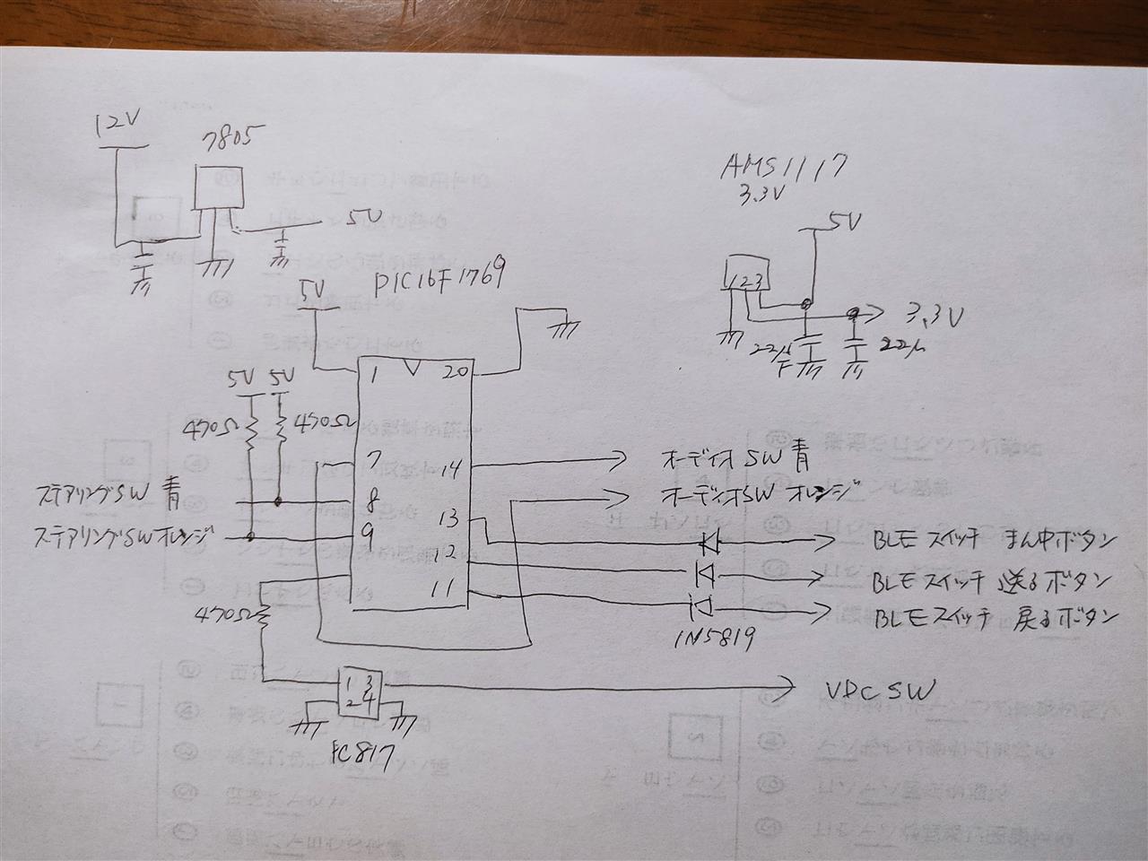
というわけで、最後に回路図とソースを載せておきます。
ソースは一部にゃんカラさんのコードを流用していることもあり、商用利用は禁止としておきます。商用でこんなことしようと思う人も需要もないと思いますが(笑)
まずは回路図。手書きで汚くてすみません(汗)
そしてソース。
/*
* File: newmain.c
* Author: saito-a
*
* Created on 2022/07/29, 21:36
*/
// PIC16F1769 Configuration Bit Settings
// 'C' source line config statements
// CONFIG1
#pragma config FOSC = INTOSC // Oscillator Selection Bits (INTOSC oscillator: I/O function on CLKIN pin)
#pragma config WDTE = OFF // Watchdog Timer Enable (WDT disabled)
#pragma config PWRTE = OFF // Power-up Timer Enable (PWRT disabled)
#pragma config MCLRE = ON // MCLR Pin Function Select (MCLR/VPP pin function is MCLR)
#pragma config CP = OFF // Flash Program Memory Code Protection (Program memory code protection is disabled)
#pragma config BOREN = OFF // Brown-out Reset Enable (Brown-out Reset enabled)
#pragma config CLKOUTEN = OFF // Clock Out Enable (CLKOUT function is disabled. I/O or oscillator function on the CLKOUT pin)
#pragma config IESO = ON // Internal/External Switchover Mode (Internal/External Switchover Mode is enabled)
#pragma config FCMEN = ON // Fail-Safe Clock Monitor Enable (Fail-Safe Clock Monitor is enabled)
// CONFIG2
#pragma config WRT = OFF // Flash Memory Self-Write Protection (Write protection off)
#pragma config PPS1WAY = ON // Peripheral Pin Select one-way control (The PPSLOCK bit cannot be cleared once it is set by software)
#pragma config ZCD = OFF // Zero-cross detect disable (Zero-cross detect circuit is disabled at POR)
#pragma config PLLEN = OFF // Phase Lock Loop enable (4x PLL is always enabled)
#pragma config STVREN = ON // Stack Overflow/Underflow Reset Enable (Stack Overflow or Underflow will cause a Reset)
#pragma config BORV = LO // Brown-out Reset Voltage Selection (Brown-out Reset Voltage (Vbor), low trip point selected.)
#pragma config LPBOR = OFF // Low-Power Brown Out Reset (Low-Power BOR is disabled)
#pragma config LVP = ON // Low-Voltage Programming Enable (High-voltage on MCLR/VPP must be used for programming)
// #pragma config statements should precede project file includes.
// Use project enums instead of #define for ON and OFF.
#define _XTAL_FREQ 32000000
#include
#include "Flash.h"
#define Blue 1
#define Orange 2
// SW ap. B
#define NC 0
#define FORWORD 1
#define PREVIOUS 2
#define VOLPLUS 3
#define VOLMINUS 4
#define MUTE 5 //IN BLUE / OUT ORANGE
#define SRC 1
#define RINGUP 2
#define RINGDOWN 3
#define MIC 4
// NAVI Logic 3.3V
#define SW0 0UL // 前 mode
#define SW1 254UL // 1.24V 次 off hook
#define SW2 440UL // 2.15V VOL+ on hook
#define SW3 581UL // 2.84V VOL- mute
#define SWNC 682UL // 3.3V
// VDC_mode definition
#define VDC_ON 0
#define VDC_MULTI 1
#define VDC_OFF 2
// BLE_sw_definition
#define BLE_SW_ON 0
#define BLE_SW_OFF 1
void init(void) {
INTCON = 0b00000000;
T1GCON = 0b00000000;
OSCCON = 0b11110000; // Internal OSC 8MHz(32MHz)
ADCON1 = 0b11100000; // Right justified, AD変換クロック 2.0 micro sec, Vss, Vdd
ANSELA = 0b00000000;
ANSELB = 0b00000000;
ANSELC = 0b11000000; // RC6,RC7
TRISA = 0b00000000;
TRISB = 0b00000000;
TRISC = 0b11000000; // RC6,RC7 is INPUT
PORTA = 0b00000000;
PORTB = 0b01110000; //RB4,RB5,RB6 をBLE_SW_OFF(HIGH)に。 RB7 をVDC SW OFFに
PORTC = 0b00000000;
// DAC for Blue wire (10bit))
DAC1CON0bits.FM = 0b0;
DAC1CON0bits.OE1 = 0b0;
// DAC1CON0bits.OE2 = 0b0; //PIC16F1769には無い出力
DAC1CON0bits.PSS = 0b00;
DAC1CON0bits.NSS = 0b00;
DAC1CON0bits.EN = 1;
// DAC for Orange wire (10bit))
DAC2CON0bits.FM = 0b0;
DAC2CON0bits.OE1 = 0b0;
// DAC2CON0bits.OE2 = 0b0; //PIC16F1769には無い出力
DAC2CON0bits.PSS = 0b00;
DAC2CON0bits.NSS = 0b00;
DAC2CON0bits.EN = 1;
// OP Amp for Blue wire
OPA1CONbits.UG = 1;
OPA1CONbits.ORPOL = 0;
OPA1CONbits.ORM = 0;
OPA1NCHSbits.NCH = 0b0000;
OPA1PCHSbits.PCH = 0b0010; // DAC1 out
OPA1CONbits.EN = 1;
// OP Amp for Orange wire
OPA2CONbits.UG = 1;
OPA2CONbits.ORPOL = 0;
OPA2CONbits.ORM = 0;
OPA2NCHSbits.NCH = 0b0000;
OPA2PCHSbits.PCH = 0b0011; // DAC2 out
OPA2CONbits.EN = 1;
}
// convert analog value to SW number
// 470R
int convSwVal(long sVal) {
int retVal;
if(sVal < 131L) {
// 0R
retVal = 1;
} else if(sVal < 393L) {
// 162R
retVal = 2;
} else if(sVal < 637L) {
// 490R
retVal = 3;
} else if(sVal < 813L) {
// 1.3KR
retVal = 4;
} else if(sVal < 947L) {
// 2.7KR
retVal = 5;
} else {
// 100KR
retVal = 0;
}
return retVal;
}
void outDAC(int Wire, unsigned long AnalogVal) {
switch(Wire) {
case Blue: // Blue wire
DAC1REFH = AnalogVal >> 8;
DAC1REFL = AnalogVal & 0xFF;
DACLDbits.DAC1LD = 0b1;
__delay_us(20);
break;
case Orange: // Orange wire
DAC2REFH = AnalogVal >> 8;
DAC2REFL = AnalogVal & 0xFF;
DACLDbits.DAC2LD = 0b1;
__delay_us(20);
break;
default:
break;
}
}
// Output to pins
void outputSwData(int wire, int SW) {
switch(wire) {
case Blue: // Blue
switch(SW) {
case NC: // (NC)
outDAC(Blue, SWNC);// (NC)
RB6 = BLE_SW_OFF;
RB5 = BLE_SW_OFF;
RB4 = BLE_SW_OFF;
break;
case VOLPLUS: // VOL +
outDAC(Blue, SW2);// VOL +
break;
case VOLMINUS: // VOL -
outDAC(Blue, SW3);// VOL -
break;
case FORWORD: // >
outDAC(Blue, SW0);// >
if (BLE_SW_OFF == RB4){ //真ん中ボタン押下中(送り長押し継続中)は送りボタンは制御しない
RB5 = BLE_SW_ON;
}
break;
case PREVIOUS: // <
outDAC(Blue, SW1);// <
RB6 = BLE_SW_ON;
break;
case MUTE: // Mute
outDAC(Orange, SW3);
break;
default:
break;
}
break;
case Orange: // Orange
if (SW != MIC){
RB7=0;
}
switch(SW) {
case NC: // (NC)
outDAC(Orange, SWNC);// (NC)
break;
case SRC: // SRC
outDAC(Orange, SW0);// SRC
break;
case MIC: // MIC
RB7 = 1;
break;
case RINGDOWN: // Ring off
outDAC(Orange, SW1);// Ring off
break;
case RINGUP: // Ring up
outDAC(Orange, SW2);// Ring up
break;
default:
break;
}
break;
default:
break;
}
}
void main(void) {
long blueVal;
int blueSw;
long orangeVal;
int orangeSw;
int vdc_mode;
char rom_data;
int time_count=0; //長押しカウンタ
int push=0; //長押しフラグ
init();
// 初期vdc設定読み出し
__delay_ms(3000);
rom_data=(char)FLASH_read(0x1f80);
if (rom_data==1){
vdc_mode = VDC_MULTI;
}
else if (rom_data==2) {
vdc_mode =VDC_OFF;
}
else {
vdc_mode= VDC_ON;
}
// 初期vdc制御
if (vdc_mode == VDC_MULTI) {
RB7 = 1;
__delay_ms(500);
RB7 = 0;
}
else if (vdc_mode == VDC_OFF){
RB7 = 1;
__delay_ms(2500);
RB7 = 0;
}
// BLEswitchペアリング処理
__delay_ms(6000);
RB4 = BLE_SW_ON;
__delay_ms(3000);
RB4 = BLE_SW_OFF;
while(1) {
// Blue wire
ADCON0 = 0b00100001; // AN8 ADC Start (RC6) 8pin
__delay_us(20);
ADCON0bits.GO = 1;
while(ADCON0bits.GO);
blueVal = ADRESL + (ADRESH * 256);
blueSw = convSwVal(blueVal);
outputSwData(Blue, blueSw);
// Orange wire
ADCON0 = 0b00100101; // AN9 ADC Start (RC7) 9pin
__delay_us(20);
ADCON0bits.GO = 1;
while(ADCON0bits.GO);
orangeVal = ADRESL + (ADRESH * 256);
orangeSw = convSwVal(orangeVal);
if(blueSw != MUTE){
outputSwData(Orange, orangeSw);
}
// vdc長押し(約5秒)で初期モード変更
if (orangeSw == MIC){
if (push == 0){
push = 1;
T1CON = 0;
TMR1H = 0;
TMR1L = 0;
PIR1bits.TMR1IF = 0;
T1CON = 0b00110001;
}
if (PIR1bits.TMR1IF == 1){
time_count++;
PIR1bits.TMR1IF = 0;
}
if (time_count == 75){
vdc_mode++;
if (vdc_mode>2){
vdc_mode = 0;
}
FLASH_erase(0x1f80);
FLASH_write(0x1f80,vdc_mode,0);
T1CON = 0;
time_count++;
}
}
// FORWARD長押しで真ん中BLEスイッチON
else if ( blueSw == FORWORD || blueSw == PREVIOUS ){
if (push == 0){
push = 1;
T1CON = 0;
TMR1H = 0;
TMR1L = 0;
PIR1bits.TMR1IF = 0;
T1CON = 0b00110001;
}
if (PIR1bits.TMR1IF == 1){
time_count++;
PIR1bits.TMR1IF = 0;
}
if (time_count == 16){ //長押し検出
if ( blueSw == FORWORD ){ //送り長押し→真ん中ボタンON、送りボタンOFF
RB5 = BLE_SW_OFF; //RB4-ONとRB5-OFFの順番を逆にするとうまく動かない
RB4 = BLE_SW_ON;
}
else if ( blueSw == PREVIOUS ){ //戻り長押し→強制ペアリング 2.2秒 送り&戻りON
RB5 = BLE_SW_ON;
__delay_ms(2200);
}
}
}
else{
push = 0;
T1CON = 0;
time_count =0;
}
}
}
---ソースここまで---
これに加えてMICROCHIP社の発行しているフラッシュメモリの解説PDFの最後の方にある
Flash.c
Flash.h
HEFlash.c
HEFash.h
を一緒にコンパイルして下さい。 Posted at 2022/09/16 21:46:09 | |
トラックバック(0) | 日記
 以前、メルカリで購入した車高調ですが、純正足の感じも少し分かったし、リアのポヨンポヨンがどうしても我慢できなかったので重い腰を上げて交換しました。